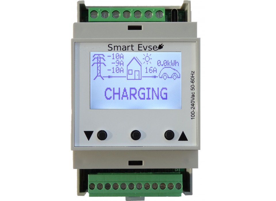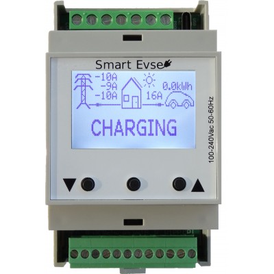
Smart charge controller for electric vehicles
The SmartEVSE can dynamically adjust the maximum power the Electric Vehicle will charge with. It supports a charging socket with locking actuator, or fixed charge cable. Up to eight SmartEVSE's can be connected together to allow for load balancing between charging stations.

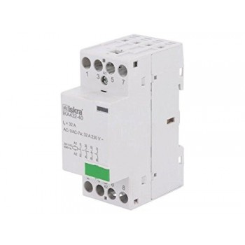
Iskra 4 pole 32A Contactor.
Specifications:
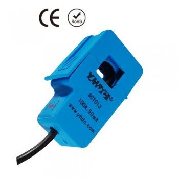
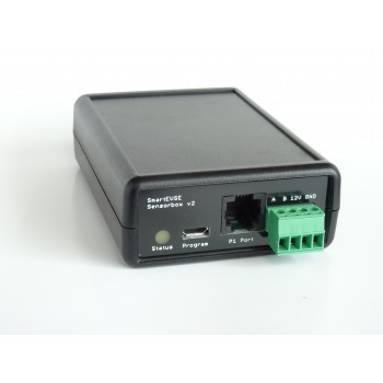
Sensorbox 2 will measure the current (and direction of current flow) on three phases, and will send this data to the SmartEVSE controller.


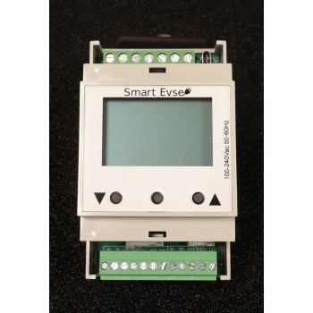


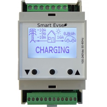
Smart charge controller for electric vehicles
The SmartEVSE can dynamically adjust the maximum power the Electric Vehicle will charge with. It supports a charging socket with locking actuator, or fixed charge cable. Up to eight SmartEVSE's can be connected together to allow for load balancing between charging stations.

Experience since 1997

Fast home delivery!

Return within 14 days of delivery
The latest manual can be downloaded here: manual
New for version 3.1:
Features:
This is only the controller, in order to build a EVSE you will also need:
This evaluation kit is intended for use for ENGINEERING DEVELOPMENT, DEMONSTRATION, OR EVALUATION PURPOSES ONLY and is not considered by Stegen Electronics to be a finished end-product fit for general consumer use. Persons handling the product(s) must have electronics training and observe good engineering practice standards. As such, the goods being provided are not intended to be complete in terms of required design-, marketing-, and/or manufacturing-related protective considerations, including product safety and environmental measures typically found in end products that incorporate such semiconductor components or circuit boards. This evaluation kit does not fall within the scope of the European Union directives regarding electromagnetic compatibility, restricted substances (RoHS), recycling (WEEE), FCC, CE or UL, and therefore may not meet the technical requirements of these directives or other related directives.
Iskra 4 pole 32A Contactor.
Specifications:
Sensorbox 2 will measure the current (and direction of current flow) on three phases, and will send this data to the SmartEVSE controller.
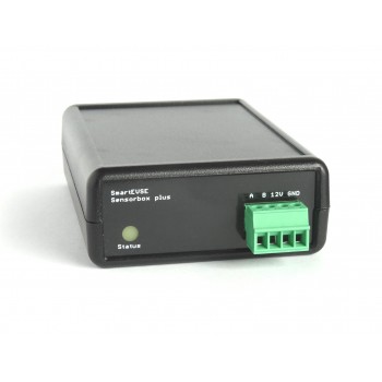
Sensorbox plus will measure the current (and direction of current flow) on three phases, and will send this data to the SmartEVSE controller.
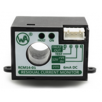
This residual current monitor will detect DC residual currents in 50Hz/60Hz AC installations.
It's primarily intended for use in Electric Vehicle charging stations to disconnect the supply to the Electric Vehicle under a DC residual fault current condition.